
Physical Sciences Grade 11
Prescribed Experiment for formal Assessment
Knowledge Area: Electricity and Magnetism
Topic: Internal resistance and Series-Parallel networks
Part 1
Aim
To determine the internal resistance of a battery
Precautions
Do not leave the switch closed at all times. The battery will run flat. Close the switch only for taking the readings on the voltmeter and Ammeter. Take your readings accurately. Do not conduct the experiment with wet hands.
Instructions
Place 4 x 1,5V cells in a cell holder in a series connection. Connect a Switch, Ammeter and a Rheostat in series to the battery. Connect the Voltmeter across the battery.
If a rheostat is not available, resistors or bulbs could be used in the place of a rheostat. The resistors or bulbs must be connected in series. One resistor/bulb must be connected first and then the resistors/bulbs be increased to two in series, three in series, etc.
Draw the electrical circuit diagram. Set the Rheostat at 10W. Close the switch and reduce the resistance in the Rheostat step by step, increasing the current at the same time. Take the ammeter and voltmeter readings in each case/step. Open the switch while recording the readings in order to spare the batteries’ life span.
Take and record a minimum of 5 readings. Interpret and analyse the data in order to determine the internal resistance. Write a conclusion and prepare a report (write-up).
Part 2
Aim:
- To determine the equivalent resistance in a Series-parallel network electrical circuit.
- To compare the experimental values of the equivalent resistance to the theoretical values.
Instructions:
Place 4 x 1.5V cells in a cell in a cell holder in a series connection. Connect a voltmeter (V1) across the battery. Connect three resistors of different resistance. One resistor must be connected in series with a voltmeter (V2) across and the other two resistors must be connected in parallel with a voltmeter across (V3). Connect a switch and an ammeter.
Draw the electrical circuit. Determine the equivalent resistance experimentally and compare the readings to the calculated values of equivalent resistance. Submit a report (write up)
INTERNAL RESISTANCE:
KNOWLEDGE AREA: ELECRICITY AND MAGNETISM
TOPIC: ELECTRIC CIRCUITS
| INTRODUCTION |
| The term ‘lost volts’ refers to the difference between the emf and the terminal voltage. The voltage is not ‘lost’. It is the voltage across the internal resistance of the battery, but ‘lost’ for use in the external circuit. The internal resistance of the battery can be treated just like another resistor in series in the circuit. The sum of the voltages across the external circuit plus the voltage across the internal resistance is equal to the emf: ε = Vload + Vinternal resistance = IRexternal + Ir Rearrange to get : V = – rI + ε in the form y = mx + c where m = -r |
Aim:To determine the internal resistance of a battery
Apparatus:
Battery, Ammeter
Voltmeter (millimeters)
Rheostat (or various resistors)
Connecting wires
Switch, Cell holder
Method:
1. Set up the circuit as shown below:
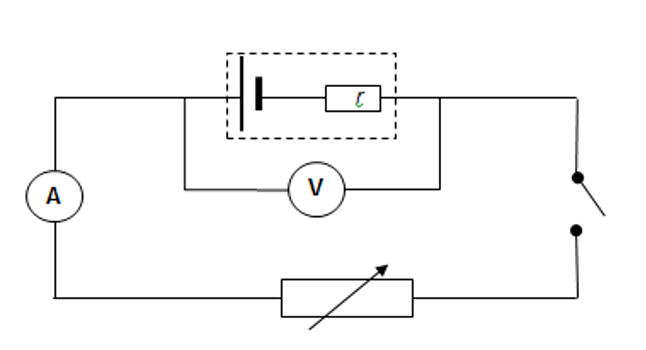
2. With the switch open, take the reading on the voltmeter and ammeter.
3. Close the switch.
4. Take readings on the voltmeter and ammeter quickly and open the switch.
5. Vary the readings of the circuit by changing the settings on the rheostat.
Close the switch and take the readings of current and potential difference. Open the switch.
6. Repeat the previous step 4 / 5 times.
7. Record the results in a suitable table (5)

Leave a Reply